Introduce
Gas turbines operate in a very high temperature range of about 1200 -1500℃, and in order to withstand these high temperatures, it is necessary to insulate the components. Thermal barrier coatings are used for this purpose. Thermal barrier coating (TBC) allows the parent material to operate at a lower temperature. They play an important role in heat insulation of gas turbines, aero-engine parts and other parts (such as turbine blades, combustion chambers, pipes and nozzle guide vanes) running at high temperature. Thermal barrier coatings are characterized by very low thermal conductivity.
TBCs usually consists of four layers:
1. Metal substrate: nickel or cobalt-based alloy.
2. Metal adhesive layer: Nicoraly or Nicoraly.
3. thermally grown oxide (TGO)
4. Ceramic topcoat.
At the peak working temperature of the adhesive layer, the temperature of the adhesive layer in the turbine usually exceeds 700℃, which leads to the oxidation of the adhesive layer and inevitably forms a third layer, namely a thermally grown oxide (1 to 10 mm thick) between the adhesive layer and the ceramic surface layer.
Yttria stabilized zirconia is used as ceramic topcoat. Pure zirconia undergoes phase transformation in different temperature ranges;
Monocline (1173)
Quadrilateral (2370)
Cubic (2690)
Melting (2700)
Zirconia can be stabilized by the matrix of different oxides. According to experience, Y2O3 is found to be the most effective stabilizer. Y2O3 stabilized tetragonal zirconia, which is more ideal for TBC application.
Current surface coatings of turbines can withstand temperatures of about 1200. Above this temperature it will fail due to thermal fatigue. In this paper, the alternative materials of thermal barrier coating are studied emphatically, so that it can withstand the temperature higher than 1200, thus improving the efficiency of turbine engine.
Methodology
This work begins with literature investigation, and we look for different implementation schemes for gas turbine blades to withstand the high working temperature of the engine. After understanding the limitations of existing solutions, we started our work. The complete workflow is shown in Figure 1.
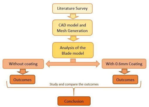
Figure 1. Workflow diagram
Starting with the introduction of CAD model and geometric cleaning, the blade is simulated. We have carried out basic research on the blade through static structure analysis and steady-state thermal analysis, so as to further study the blade. The complete workflow of the simulation study is shown in Figure 2.

Figure 2. Flow chart of simulation study
Prerequisites for simulation research
CAD model:
The CAD model of gas turbine blade shown in fig. 3 is taken from GRABCAD. Convert the further model into STEP neutral format, and after importing the model, edit it in Design Modeler to perform geometric cleaning.
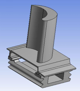
Figure 3. CAD model of turbine blade
Grid generation:
Mesh generation is completed in using the default automatic mesh option in ANSYS mechanical. According to the complexity of the model and the thickness of the coating, the size of the whole element varies from 0.6 mm to 22 mm. Figures 4 and 5 show the full mesh blade models with and without topcoat, respectively.
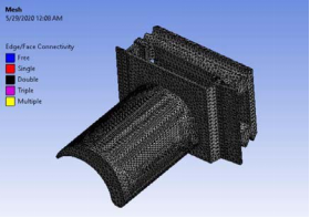
Figure 4. Grid generation of uncoated blades
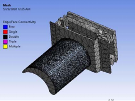
Fig. 5. Mesh generation of blades with 0.6 mm coating.
Loads and boundary conditions:
For the analysis model, the load is the mechanical force and thermal load acting on the underutilized blade, and the boundary condition is the environmental factor that affects the behavior of the underutilized blade.
Static structural analysis of loads and boundary conditions;
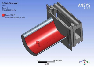
Figure 6. Force of 980 N acting on the blade.
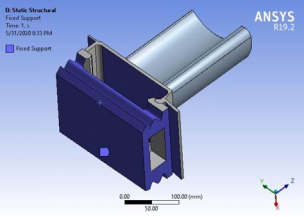
Figure 7. Fixing bracket
The rotor in a turbine consists of a shaft and an impeller. Turbine impeller is a dynamic balancing device. A turbine wheel is called a turbine disk without blades. When the blades are installed, the disc is called the turbine wheel. The blade is mounted on the disk through a groove or notch made on the disk to place the blade. Once the blade is loaded into the slot, a locking piece or rivet is used to keep the position of the blade on the disk. The fir-tree design at the end of the blade specifies the fixed support boundary conditions, as shown in Figure 7. The assembly rotates at a very high speed, which imposes a very high load of up to 980N on the blade, as shown in Figure 6.
Static structural analysis of loads and boundary conditions;
The operating temperature of these engines is very high due to the combustion of fuel in the engines. Most parts of the engine are exposed to extreme temperatures. In which turbine blades are always exposed to the highest operating temperature of the engine. Because the hot exhaust gas passes directly through these blades. In most gas turbines, the current operating temperature is 1200. Therefore, we apply forced convection to the upper and lower surfaces of the blades, as shown in Figure 8.
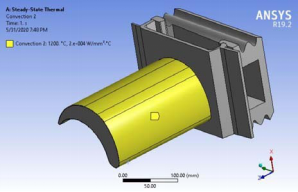
Figure 8.1200 Convection on Blade Surface Caused by Hot Air Flow
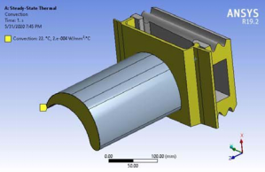
Figure 9. Convection in other areas of the blade exposed to ambient air.
Even the temperature at the edge of the disk is very high, far higher than the temperature inside the disk. Therefore, in addition to rotational stress, thermal stress will also occur. In order to reduce this thermal stress, cooled ambient air is transferred to the surface of the disk, which will help reduce the temperature of the disk edge. Therefore, we apply free convection to the blade area near the edge of the disk, as shown in Figure 9. In addition, the edge of the disk absorbs heat from the blade by conduction, as shown in Figure 10.
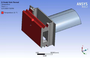
Figure 10. Contact-induced blade conduction
Prerequisites for simulation research
Analysis of blades without thermal barrier coating;
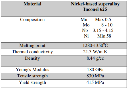
We analyzed the blade model without any coating. Turbine blades are made of nickel-based superalloy Inconel 625 [3], and their properties are shown in Table 1 below.
Table 1. Properties of Nickel-based Superalloys
Analysis of gas turbine blades with thermal barrier coating;
We consider three kinds of materials for coating gas turbine blades, which are (a) titanium carbide, (b) tantalum carbide and (c) zirconium carbide. These materials are chosen because of their low density, low thermal conductivity and high melting temperature. We carried out static structure analysis and steady thermal analysis, considering the coating thickness of 0.6 mm respectively. Table 2 contains all the characteristics of these three materials needed for simulation.
Table 2. Characteristics of materials

Compared with tantalum carbide and zirconium carbide, the total deformation of blade model with tantalum carbide coating is higher.
Because the material is brittle in nature, we calculated the maximum principal stress in all three cases, and found that compared with the other two blade models, the induced stress of tantalum carbide coated blade model is the smallest.
The temperature isoline generated by steady-state thermal analysis is helpful for us to understand the temperature change of blade model. The highest temperature of all three models is reached in the coating area.
From the steady-state thermal analysis, the maximum heat flux of tantalum carbide model is the lowest, followed by zirconium carbide and titanium carbide blade model. The comparative study of these materials has produced a good correlation with analysis.
Conclusion
From the simulation study of blade model without thermal barrier coating, it is obvious that coating is essential for gas turbine blades to work effectively at high temperature. We analyzed the blade models with different coating materials.
From the static structure analysis, we found that compared with the other two coating materials, the blade coated with tantalum carbide has smaller induced maximum stress. Therefore, it is obvious that tantalum carbide can bear a higher load than the other two materials.
From the steady-state thermal analysis, we find that the maximum heat flux of the blade model with tantalum carbide coating is smaller than that of the other two models.
Therefore, tantalum carbide is the best substitute for gas turbine blade coating.